
To determine the correct bearing puller size and type for an angle grinder, you must identify the specific bearing’s location and measure its physical dimensions. Angle grinders do not use a single, universal bearing size. Instead, they contain multiple bearings of varying dimensions, typically requiring a small mechanical puller with a jaw spread of 10mm to 50mm, or a specialized blind hole bearing puller with expanding collets for recessed motor bearings.
Matching the tool to your specific repair task requires evaluating the jaw capacity, the reach of the puller arms, and the physical clearance inside the grinder’s housing. Using the wrong style or an oversized automotive puller can easily destroy the delicate aluminum gearcase or snap the armature shaft. By understanding the internal architecture of your power tool and matching it to the correct puller specifications, you can safely extract worn bearings without compromising the integrity of the tool.
Understanding Why There Is No Universal Bearing Puller Size
An angle grinder is a compact, high-speed power tool that relies on several strategically placed bearings to support its rotating components. Because these bearings perform different functions under varying loads, they differ significantly in size, design, and accessibility. A single, one-size-fits-all bearing puller cannot accommodate the diverse configurations found within even a single grinder, let alone across different brands and models.
Products mentioned in this guide
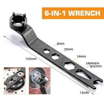
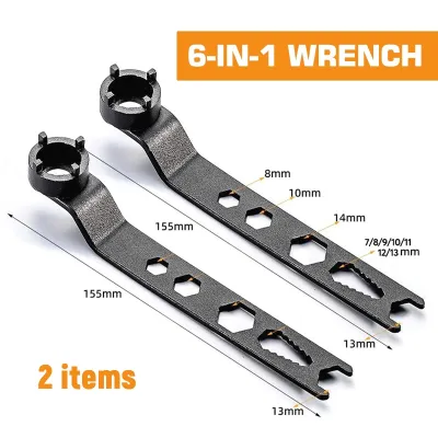
Prices are valid at publication and may change. Please refer to the product page for the latest price.
To select the right extraction tool, you must first differentiate between the primary bearing locations inside the grinder. The spindle and gearcase assembly houses the larger bearings that support the grinding disc flange. These bearings experience heavy axial and radial loads during cutting or grinding operations and are typically housed in the metal gear head. Because they are located near the output shaft, they are generally larger and more accessible than the other internal bearings, though they are often pressed tightly into the gear housing or onto the spindle shaft.
In contrast, the armature and rotor assembly within the motor housing relies on smaller, high-speed bearings. The rear armature bearing sits at the very back of the motor, nestled deep within the plastic handle or housing, while the front armature bearing sits just behind the pinion gear. These bearings are designed for exceptionally high rotations per minute (RPM) rather than heavy impact loads. They are frequently recessed, mounted flush against the armature windings, or positioned deep within tight plastic cavities where standard external puller jaws cannot reach.
Furthermore, the physical size of the angle grinder itself dictates its internal architecture. A standard 4-inch (100mm) or 5-inch (125mm) angle grinder—the types most commonly used in residential and light commercial workshops—utilizes compact bearings with outer diameters often ranging from 19mm to 32mm. Conversely, a heavy-duty 9-inch (230mm) industrial angle grinder features much larger shafts, heavier gears, and robust bearings designed to withstand extreme industrial use. A puller designed for a 9-inch grinder’s spindle bearing will be far too bulky to fit inside the cramped motor housing of a 4-inch DIY model.
Before purchasing any removal equipment, always consult your specific tool’s service manual or exploded parts diagram to identify the exact bearing part numbers and dimensions. If documentation is unavailable, use a digital caliper to physically measure the bearing’s outer diameter (OD), inner diameter (ID), and the available clearance behind the bearing race. Guessing the required puller size based solely on the external dimensions of the grinder housing almost always results in purchasing an incompatible tool that cannot grip the bearing securely.
How to Match Puller Specifications to Your Angle Grinder
Selecting a bearing puller requires matching the mechanical specifications of the puller to the physical dimensions of the target bearing and the surrounding tool components. To ensure a successful repair, you must evaluate three critical specifications: jaw spread, reach, and pull force.

Jaw Spread (Capacity)
The jaw spread refers to the maximum distance the puller’s jaws can open while maintaining a secure, parallel grip on the target object. For angle grinder repairs, the minimum and maximum jaw spread must align with the outer diameter of the bearing. If the jaw spread is too large, the puller hooks will not close tightly around a small 22mm armature bearing, causing them to slip off under tension. Look for micro or mini gear pullers specifically rated for small-diameter bearings, typically starting as low as 10mm of spread.
Reach (Length)
The reach of a puller defines the maximum working depth the arms can extend from the tip of the forcing screw to the jaw hooks. This dimension is highly critical when extracting bearings from long armature shafts. The puller arms must be long enough to clear the length of the shaft, any integrated cooling fans, and the surrounding housing, allowing the hooks to seat flat against the back of the bearing race. At the same time, the forcing screw must have enough thread travel to push fully against the center of the shaft until the bearing is completely free.
Pull Force (Tonnage)
While heavy industrial machinery requires pullers rated for 5 to 10 tons of force, small power tools require significantly less mechanical tonnage. However, do not underestimate the force required to break a seized bearing loose. In the tropical climate of the Philippines, high relative humidity and exposure to moisture can cause rapid oxidation, leading to “rust welding” between the steel bearing inner race and the steel armature shaft. A high-quality mechanical screw puller rated for 1 to 2 tons provides more than enough mechanical advantage to break this rust bond.
It is vital to avoid using oversized, high-tonnage automotive pullers on small power tools. Applying excessive torque via a large automotive tool can easily bend or snap the thin steel armature shaft, strip the delicate threads on the spindle, or crack the cast magnesium or aluminum gear housing. The key is using a compact, precisely sized tool that applies concentrated, evenly distributed force directly to the inner bearing race.
Recommended Puller Types for Confined Power Tool Spaces
Because the internal components of an angle grinder are packed tightly to minimize the tool’s overall size, standard utility pullers are rarely effective. To build a reliable power tool repair kit, look for specialized puller configurations designed specifically for tight clearances and delicate shafts.
Two-Jaw and Three-Jaw Gear Pullers
Two-jaw and three-jaw mechanical gear pullers are the most common tools used for exposed bearings, such as those found on the spindle shaft or the accessible end of the armature. Whenever space permits, a three-jaw puller is the preferred choice. The three-point configuration distributes the pulling force more evenly across 120-degree intervals, significantly reducing the risk of the bearing tilting or binding on the shaft during removal. This even distribution also prevents the puller from slipping off the rounded edges of the bearing.
However, the compact gearcases of many angle grinders present severe spatial limitations. When the adjacent metal housing walls or gear teeth block the positioning of a third arm, a two-jaw puller becomes necessary. Two-jaw pullers require careful alignment to ensure the force remains perfectly parallel to the shaft, but their narrower profile allows them to slip into tight lateral clearances where a three-jaw configuration cannot fit.
Blind Hole Bearing Pullers
One of the most challenging repairs is removing a bearing that is pressed flush into a recessed cavity, such as the needle bearing or ball bearing located at the bottom of the gear housing, or the rear armature bearing seated deep within the plastic motor casing. In these scenarios, there is no gap behind the bearing for standard external jaws to grip. A blind hole bearing puller set is the only viable tool for this task.
These specialized kits utilize expanding collets that are inserted directly into the center bore (inner race) of the bearing. Turning the expansion wedge or nut flares the collet outward, locking its ridges securely against the inner lip of the bearing. Once anchored, a slide hammer or a bridge-style pulling frame is attached to the collet to draw the bearing straight out of its recess. This method extracts the bearing without applying any prying force to the delicate outer plastic or aluminum housing.
Small Internal/External Combination Pullers
For general power tool maintenance, a small internal/external combination puller—often referred to as a micro-bearing puller or a battery terminal puller—is highly versatile. These compact tools feature reversible jaws with exceptionally fine, low-profile hooks. The tips of the jaws are often ground down to less than 2mm in thickness, allowing them to slide into the microscopic gap between the bearing and the armature windings or cooling fan.
These combination pullers are specifically scaled for small electric motors. They typically feature a fine-threaded forcing screw that allows for highly controlled, incremental pressure. This precise control is essential when working with small bearings (such as the 608 or 607 series commonly found in 100mm grinders) where a sudden, uncontrolled burst of force could damage the delicate copper commutator segments nearby.
Safe Removal Techniques and Hard Safety Boundaries
Working with mechanical pullers and press-fit assemblies carries inherent risks. Bearings are made of hardened steel, which is highly brittle; under extreme tension, a seized bearing can shatter, sending sharp metal fragments flying at high velocity. Following a disciplined, safety-first workflow is essential to protect both yourself and the tool.
Preparation and Personal Protective Equipment (PPE)
Before beginning any disassembly, always disconnect the angle grinder from its power source by unplugging the cord or removing the battery pack. Clear your workspace of debris and put on high-impact safety glasses and heavy leather work gloves. The gloves not only protect your hands from sharp gear teeth and housing edges but also absorb energy if a puller jaw slips under load.
Penetrating Oil and Dwell Time
If the bearing exhibits signs of corrosion or has been exposed to the humid, salty air common in coastal regions of the Philippines, do not attempt to pull it dry. Apply a generous amount of high-quality penetrating oil directly to the junction where the bearing’s inner race meets the shaft. Allow the oil to sit for at least 15 to 30 minutes to penetrate the microscopic gaps and dissolve any binding rust. This simple step drastically reduces the torque required to break the press-fit bond.
Controlled Heat Application
When a bearing is tightly pressed into an aluminum or magnesium gear housing, you can leverage the thermal expansion properties of the metals to ease removal. Aluminum expands at a faster rate than steel when heated. Using a professional heat gun, gently apply heat to the exterior of the metal housing surrounding the bearing for 1-2 minutes. This slight expansion of the housing relaxes its grip on the steel outer race.
Warning: Never use an open-flame torch (such as a propane or butane torch) for this process. The intense, uncontrolled heat of an open flame can easily melt internal plastic components, char the protective insulation on the armature windings, distort the rubber seals of adjacent bearings, or permanently ruin the heat treatment of the metal housing.
Hard Safety Boundary
When operating the bearing puller, apply torque to the forcing screw slowly and smoothly using a hand wrench. Do not use pneumatic or electric impact wrenches on small power tool pullers, as the rapid, violent hammering action will strip the puller threads or shatter the bearing.
If you apply steady, reasonable hand pressure and the bearing does not budge, stop immediately. Do not slip a cheater pipe over your wrench for extra leverage, and do not strike the forcing screw with a hammer. Forcing a seized bearing beyond reasonable limits will inevitably bend the armature shaft, strip the rotor shaft threads, or crack the gearcase. If the bearing remains immovably stuck after applying penetrating oil and controlled heat, take the disassembled component to a qualified power tool repair professional who has access to hydraulic shop presses and specialized extraction jigs.
Repair vs. Replace: Assessing Your Angle Grinder's Condition
Before investing time and money into sourcing a bearing puller and replacement parts, evaluate whether the angle grinder is a candidate for a successful repair, or if it has suffered damage that warrants replacing the entire tool.
Begin by diagnosing the specific symptoms of the failure. Common indicators of worn or failing bearings include:
- A high-pitched, harsh grinding or squealing noise during operation.
- Excessive, unusual vibration felt through the handle.
- Visible lateral play or wobbling in the grinding spindle.
- A distinct burning smell or smoke emerging from the motor vents.
If you detect a burning smell or notice that the grinder lacks power, disassemble the tool and closely inspect the motor components before purchasing a puller. When a bearing fails completely, it can allow the armature (the spinning rotor) to run off-center. This causes the rotor to physically drag against the stator (the stationary field coils), generating extreme friction. Inspect the copper wire windings on both the armature and the field coils. If you see deep physical scoring on the metal laminations, melted copper wire, or blackened, charred insulation, the motor has suffered a catastrophic electrical short. In this state, replacing the bearings will not restore the tool to operation.
Conversely, if the motor windings are clean, bright copper, and free of physical damage, replacing a noisy or rough bearing is a highly cost-effective repair. Standard deep-groove ball bearings used in power tools are widely available and extremely inexpensive, typically costing between ₱50 and ₱200. In contrast, a high-quality, professional-grade angle grinder can cost anywhere from ₱3,500 to over ₱8,000 in the Philippines. If the motor is electrically sound, performing a bearing replacement using the correct puller is a highly economical way to extend the lifespan of your tool by several years.
Frequently Asked Questions (FAQ)
Can I use an automotive steering wheel puller on an angle grinder?
No, you should not use an automotive steering wheel puller or a standard heavy-duty automotive gear puller on an angle grinder. Automotive pullers are engineered for large, heavy vehicle components and are far too bulky for power tools. Their jaw hooks are typically too thick to slide behind the tight clearances of an armature bearing, and their overall physical size prevents them from fitting inside the cramped plastic or metal housings of a grinder. Furthermore, the massive force generated by these large tools can easily bend the small, delicate steel shafts of a power tool or crack its lightweight aluminum castings.
What is the most common bearing size in a standard angle grinder?
While there is no universal standard across all manufacturers, many popular 4-inch (100mm) and 5-inch (125mm) angle grinders commonly utilize standard metric deep groove ball bearings. The 608 bearing (8mm inner diameter, 22mm outer diameter, 7mm width) is frequently used as the rear armature bearing in many small power tools. Other common sizes include the 6201, 6000, and 629 series bearings. However, because manufacturers frequently change internal specifications across different model generations, you must always read the alphanumeric code stamped on the rubber seal of your existing bearing or measure it with a caliper rather than purchasing replacements based on general assumptions.
Community discussion
Share your experience or ask a question. Comments are reviewed before publication.