
The 3-pin connector in your car’s ignition system serves as the vital electrical bridge between the engine control unit (ECU) and the individual ignition coil. In modern coil-on-plug setups, this small plastic plug delivers the power, ground, and precise timing signals required to generate the high-voltage spark that ignites the fuel-air mixture in the cylinders.
In tropical climates like the Philippines, where high humidity, heavy seasonal rains, and intense engine bay heat are common, ignition connectors are subjected to severe environmental stress. Plastic housings can become brittle, and metal terminals can corrode over time. Understanding how this connector functions allows you to diagnose ignition issues accurately before spending money on replacement parts.
The Role of the 3-Pin Connector in Modern Ignition Systems
Modern vehicles have largely transitioned from older distributor-based ignition systems to highly efficient coil-on-plug designs. In older setups, a single central coil generated high voltage and distributed it through long spark plug wires. Modern engines instead place an individual ignition coil directly on top of each spark plug, eliminating the need for high-voltage spark plug wires and reducing energy loss.
Products mentioned in this guide
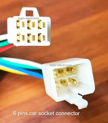
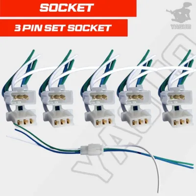
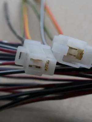
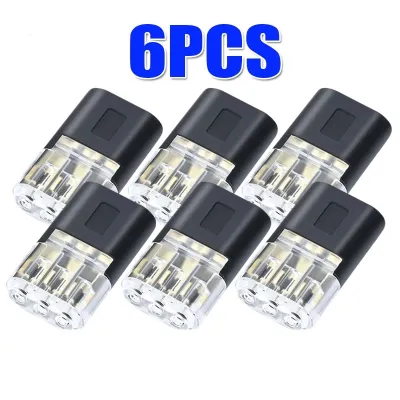
Prices are valid at publication and may change. Please refer to the product page for the latest price.
This decentralized design requires a reliable way to distribute low-voltage power and control signals to each individual cylinder. The 3-pin connector fulfills this role by linking the main engine wiring harness directly to the ignition coil. It acts as a secure gateway, ensuring that the low-voltage electrical current and timing commands from the vehicle’s computer reach the coil’s primary winding without interruption.
Because each cylinder has its own dedicated coil and connector, a failure in a single 3-pin plug will typically affect only that specific cylinder. This localized design helps prevent total engine failure, but it requires drivers to be able to isolate which connector or coil is causing the issue when troubleshooting a misfire.
Decoding the Pins: Power, Ground, and ECU Signal
To troubleshoot an ignition issue effectively, it helps to understand what each of the three pins inside the connector does. While physical layouts vary, a standard 3-pin ignition connector typically carries three distinct circuits: the power supply, the ground, and the trigger signal.

The power pin delivers switched 12-volt electrical current from the vehicle’s battery via the ignition relay. This provides the primary electrical energy that the coil will eventually step up into a high-voltage spark. The ground pin completes the electrical circuit, connecting back to the vehicle’s chassis, engine block, or directly to the ECU’s ground network to ensure a clean, stable return path for the current.
The third pin carries the low-voltage trigger signal from the ECU. This timing signal is a rapid pulse that tells the ignition coil’s internal transistor exactly when to interrupt the primary current flow. This interruption collapses the magnetic field inside the coil, inducing the massive voltage spike needed to fire the spark plug.
It is critical to note that pin positions, wire colors, and terminal configurations are not universal across different vehicle makes and models. Assuming a universal pinout can lead to incorrect multimeter readings, blown fuses, or permanent damage to the sensitive ECU. Always consult your vehicle’s official factory service manual or wiring diagram to verify the exact pin layout before performing any electrical tests.
Symptoms That Point to a Connector Issue
Distinguishing between a failed ignition coil, a worn spark plug, and a faulty 3-pin connector can be challenging because they all produce similar engine misfire symptoms. However, certain clues point directly to a connector or wiring harness problem.
Intermittent misfires that seem to worsen with engine vibration, rough roads, or thermal expansion are classic signs of a loose connection. If the plastic locking tab on the connector is cracked or missing, the plug can back away from the coil terminals just enough to break contact temporarily. As the engine vibrates or heats up, the connection fluctuates, causing sporadic misfires that disappear and reappear unpredictably.
Another diagnostic clue involves reading trouble codes with an OBD-II scanner. If you retrieve a cylinder-specific misfire code, such as P0301 for cylinder 1, a common diagnostic step is to swap the ignition coil from cylinder 1 to cylinder 2. If the misfire code remains on cylinder 1 after the swap, the ignition coil itself is functioning correctly. This indicates that the problem lies elsewhere in the cylinder, often pointing to a damaged 3-pin connector or its wiring.
Visual inspections can also reveal obvious physical damage. Look closely at the connector housing for signs of melting, which can occur if the wiring harness runs too close to hot exhaust components. Inspect the metal terminals inside the plug for green or white corrosion, which restricts electrical flow, and check for pushed-back pins that fail to make physical contact with the coil.
How to Inspect and Test the Connector Safely
Before performing any electrical diagnostics, establish a safe working environment. Ensure the vehicle’s engine is turned off, the key is removed from the ignition, and the engine bay has cooled down completely to prevent burns. Always refer to your vehicle’s original manufacturer instructions for specific safety precautions and wiring schematics before handling electrical components.
Begin with a thorough visual and physical inspection of the wiring harness. Gently wiggle the connector housing to check if it is securely seated on the ignition coil. Examine the plastic locking clip; if it does not click tightly into place, the connector must be secured or replaced. Inspect the wires entering the back of the plug for cracked insulation, exposed copper, or extreme stiffness caused by heat degradation.
To perform basic electrical tests, you will need a digital multimeter. Set the multimeter to measure DC voltage and turn the vehicle’s ignition key to the “ON” position without starting the engine. Carefully probe the terminal corresponding to the power wire while grounding the black multimeter lead to a clean metal part of the engine block. The meter should display battery voltage, typically around 12 volts.
Next, turn the ignition off and switch your multimeter to the resistance or continuity setting. Probe the ground terminal on the connector and connect the other lead to the engine ground to verify a low-resistance path. If you suspect the ECU trigger signal is missing, or if the wiring harness shows extensive heat damage beyond the connector plug, stop testing. Diagnosing complex ECU signals requires specialized tools like an oscilloscope, and attempting to probe these circuits without professional guidance can permanently damage the vehicle’s computer. In these cases, consult a qualified automotive technician.
Frequently Asked Questions (FAQ)
Can I temporarily repair a broken locking tab on the 3-pin connector?
A broken locking tab is a common issue because engine heat makes the plastic connector housing brittle over time. While using zip ties or electrical tape is a common roadside quick fix, these methods are highly unreliable for long-term use. Engine vibrations and intense heat will cause tape to lose its adhesion and zip ties to stretch or slip, leading to intermittent connection failures. Additionally, a broken tab often compromises the weather-resistant silicone seal inside the plug, allowing moisture to enter and cause rapid corrosion. If the locking tab is broken, the connector pigtail should be replaced as soon as possible to prevent unexpected engine misfires.
Do I need to replace the entire engine wiring harness if the connector is melted?
No, you do not need to replace the entire engine wiring harness if the damage is localized to the connector. If only the plastic plug and the immediate few centimeters of wire are melted or cracked, you can perform a localized repair by splicing in a new 3-pin connector pigtail. This involves cutting away the damaged section of wire and connecting the new pre-wired plug using proper automotive soldering techniques and adhesive-lined heat-shrink tubing to seal out moisture. However, if the melting extends deep into the main wiring loom, or if the damage was caused by an internal short circuit rather than external engine heat, a professional diagnostic assessment is required to ensure the underlying electrical issue is resolved safely.

Community discussion
Share your experience or ask a question. Comments are reviewed before publication.